Table of Contents
Introduction
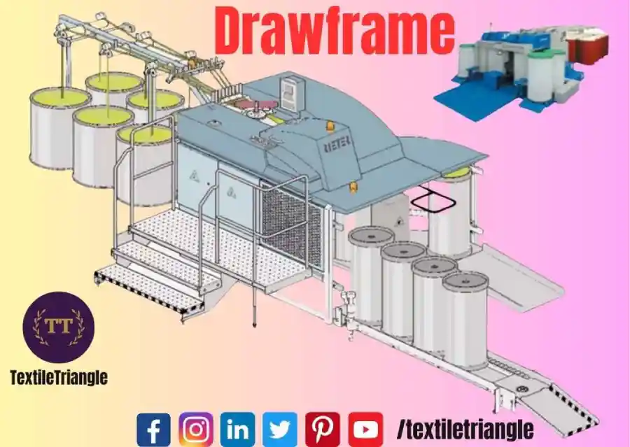
What is Drawframe ?: A drawframe is a machine used in the spinning process to convert slivers (a loose collection of fibers) into a more uniform and continuous strand called a roving. Autoleveller technology is incorporated into drawframes to ensure consistent and uniform quality of the roving.
Draw frame Auto Leveller
The primary function of an autoleveller in a drawframe is to regulate the sliver draft, which is the ratio of delivery speed to the speed at which the sliver is fed into the machine. The autoleveller system continuously monitors the sliver thickness and adjusts the draft to compensate for any irregularities. It achieves this by controlling the speed of the drafting rollers, which helps to maintain a consistent sliver thickness and thus a uniform roving.
The autoleveller system typically consists of sensors or detectors that measure the sliver thickness at various points along its length. These sensors can be optical, capacitive, or piezoelectric, depending on the specific technology used. The measurements are then fed into a control system, which compares the actual sliver thickness to the desired thickness and calculates the necessary adjustments to the draft.
By continuously monitoring and adjusting the sliver draft, the autoleveller helps to minimize variations in yarn quality caused by fluctuations in fiber properties, irregularities in the spinning process, or changes in the raw material. It plays a crucial role in ensuring consistent yarn strength, evenness, and other desired characteristics.
Open Loop Autolevelling
Open loop autolevelling, also known as feed-forward autolevelling, is a type of control system used in drawframes to maintain a consistent sliver thickness during the drafting process. Unlike closed loop autolevelling systems, which rely on feedback from sensors to make adjustments, open loop autolevelling operates based on pre-programmed calculations without actively measuring the sliver thickness.
The input material is measured for linear density or thickness by a measuring unit. The signal is processed and compared with set value by signal processing unit. If deviation exists, then servomotor is instructed to change the speed of drafting rollers to adjust the draft in other to reduce the irregularity of the output material.
Objective of Drawframe
The main objective of a drawframe in the textile industry is to convert the coarse and irregular sliver, which is a loose collection of fibers, into a finer and more uniform strand called a roving. The drawframe performs several functions to achieve this objective:
- Drafting: The drawframe applies a controlled stretching or elongation to the sliver, which helps align the fibers in a parallel arrangement and reduce the sliver thickness. This process is known as drafting and is achieved by passing the sliver through a series of pairs of drafting rollers rotating at different speeds.
- Autolevelling: The drawframe incorporates autoleveller technology to ensure consistent and uniform quality of the roving. Autolevelling systems monitor the sliver thickness and make adjustments to the drafting process to compensate for any irregularities, resulting in a more uniform roving.
- Doubling: In addition to drafting, the drawframe may also perform doubling, which involves combining multiple slivers together to increase the strand’s fineness and improve uniformity. Doubling helps to achieve a more consistent roving by blending fibers from different slivers.
- Contamination removal: The drawframe may have mechanisms or devices to remove contaminants such as short fibers, trash, and impurities from the sliver. These contaminants can negatively impact the yarn quality, so their removal is an important objective.
The drawframe’s objective is to transform the initial sliver, which is coarse, irregular, and contains impurities, into a finer, more uniform, and cleaner roving. The resulting roving can then be further processed in subsequent spinning operations to produce high-quality yarn with desirable characteristics such as strength, evenness, and uniformity.
Principle of Drawframe
Carding process separates fibres in to individual form and also removes the remaining portion of impurities left by the blow room. During the transfer of the fibres from the cylinder to the fibre hook surfaces in the fibres arise. About 50% of the fibres in the card sliver has trailing hooks,15% fibres have leading hooks and 15% of the fibres have double hooks and only a small portion(20%) of the fibres remain straight.In order to produce a strong and uniform yarn it is necessary to straighten and align the fibres and to improve the eveness of the sliver.All these objectives are achieved by drawing process.
The principle of a drawframe in the textile industry is based on the concept of drafting, which involves elongating and thinning the sliver of fibers to create a more uniform and finer strand known as roving. The drawframe operates on the following principles:
- Drafting: The drawframe uses a series of pairs of drafting rollers rotating at different speeds to stretch and reduce the sliver thickness. The sliver is fed through the nip point between the front and back rollers, and the speed difference between these rollers creates a pulling or drafting action. This elongates the sliver and aligns the fibers in a parallel arrangement, resulting in a more uniform strand.
- Roller settings: The drawframe has adjustable settings for the distance between the front and back rollers, known as the drafting zone. By changing the roller settings, the drawframe can control the amount of elongation and thinning applied to the sliver. The roller settings are determined based on factors such as fiber properties, desired sliver thickness, and the specific requirements of the spinning process.
- Autolevelling: Drawframes often incorporate autoleveller systems to maintain a consistent sliver thickness. These systems use sensors or detectors to measure the sliver thickness at various points along its length. The measurements are then used to make adjustments to the drafting process, such as controlling the speed of the drafting rollers, to compensate for any irregularities and ensure a uniform sliver thickness.
- Doubling: In some drawframes, doubling is also performed. This involves combining multiple slivers together to increase the strand’s fineness and improve uniformity. Doubling helps to blend fibers from different slivers and further enhance the uniformity of the roving.
By applying the principles of drafting, roller settings, autolevelling, and optionally doubling, the drawframe transforms the coarse, irregular, and often contaminated sliver into a finer, more uniform, and cleaner roving. This roving can then be processed in subsequent spinning operations to produce high-quality yarn. The drawframe plays a crucial role in achieving yarn characteristics such as strength, evenness, and uniformity, which are essential for textile production.
Process Parameter for Cotton and its blends
When processing cotton and its blends in a drawframe, several key process parameters need to be considered to achieve optimal results. These parameters help in controlling fiber alignment, sliver evenness, and overall drawing quality. Here are some important process parameters for cotton and its blends in the drawframe:
- Roller Settings: Adjusting the roller settings, including nip gap and roller speeds, is crucial for achieving the desired drafting effect. Fine-tuning these settings based on the fiber properties and blend composition helps in controlling the drawing process.
- Draft Ratio: The draft ratio, defined as the ratio of delivery speed to feed speed, determines the extent of elongation and thinning of the sliver. Selecting an appropriate draft ratio for cotton and its blends ensures optimal drawing quality and control over the drafting force.
- Autolevelling System: Utilizing an autolevelling system in the drawframe helps in maintaining a consistent sliver thickness and reducing variations in fiber blending. Calibrating and optimizing the autolevelling parameters based on the fiber characteristics and blend composition is important for achieving desired results.
- Tension Control: Effective tension control mechanisms, such as tension rollers or autolevelling systems, are necessary for maintaining consistent tension throughout the drafting process. This helps in minimizing force fluctuations, ensuring uniform drafting, and improving sliver quality.
- Fiber Preparation: Proper fiber opening, cleaning, and blending processes prior to the drawframe are essential for cotton and its blends. Adequate cleaning and blending ensure uniformity and reduce impurities, resulting in improved drawing performance.
- Monitoring Systems: Implementing real-time monitoring systems and sensors allows operators to monitor key parameters such as sliver thickness, evenness, and drafting force. Monitoring these parameters provides valuable feedback for making necessary adjustments and maintaining optimal processing conditions.
- Maintenance and Calibration: Regular maintenance and calibration of the drawframe machine are crucial for consistent performance. This includes cleaning and inspecting drafting components, checking roller alignment, and ensuring proper functionality of tension control systems.
It is important to note that the specific process parameters may vary depending on the specific cotton type, blend composition, and desired end product requirements. Therefore, operators should conduct trials, analyze results, and make adjustments accordingly to achieve the best possible drawing quality for cotton and its blends in the drawframe.
Drawframe Calculations
Drawframe calculations involve various parameters and formulas used to determine the settings and adjustments required for achieving the desired drafting and autolevelling in the drawframe machine. These calculations take into account factors such as fiber properties, sliver characteristics, target sliver thickness, and machine specifications. Here are some common drawframe calculations:
- Draft Ratio: The draft ratio is the ratio of the delivery speed of the drawframe to the feed speed of the sliver. It determines the amount of elongation and thinning applied to the sliver. The draft ratio is calculated using the formula: Draft Ratio = Delivery Speed / Feed Speed
- Drafting Percentage: The drafting percentage is the percentage reduction in sliver thickness achieved during the drafting process. It is calculated using the formula: Drafting Percentage = (1 – (1 / Draft Ratio)) * 100 The drafting percentage helps in determining the extent of elongation and thinning of the sliver.
- Desired Sliver Thickness: The desired sliver thickness is typically determined based on the specific requirements of the spinning process or yarn specifications. It is specified in terms of linear density or count, such as tex, denier, or Ne.
- Autolevelling Correction: Autolevelling systems in drawframes make adjustments to maintain a consistent sliver thickness. The autolevelling correction is calculated based on the difference between the actual sliver thickness and the desired sliver thickness measured by sensors. The correction value is used to control the speed of the drafting rollers to achieve the desired thickness.
- Roller Settings: The roller settings determine the drafting zone or distance between the front and back rollers. The roller settings are adjusted to achieve the desired draft ratio and drafting percentage based on the fiber properties and sliver characteristics.
It is important to note that specific drawframe calculations may vary based on machine design, technology, and manufacturer. The calculations mentioned above provide a general overview of the parameters commonly considered in drawframe operations. Drawframe operators and technicians are responsible for making appropriate calculations and adjustments to optimize the drafting process and ensure the production of consistent and uniform roving.
Draw Frame: Defects & Remedies
Drawframe defects refer to common issues or problems that can arise during the operation of a drawframe in the textile industry. These defects can negatively affect the quality of the roving or result in production inefficiencies. Here are some common drawframe defects and their possible remedies:
- Sliver Breakage:
- Defect: Sliver breaks frequently during the drafting process.
- Possible Causes: Excessive drafting, inadequate fiber cohesion, roller misalignment.
- Remedies: Adjust the roller settings to reduce excessive drafting, ensure proper fiber blending and cohesion, check and align the rollers.
- Sliver Unevenness:
- Defect: Inconsistencies in sliver thickness along its length.
- Possible Causes: Uneven drafting, improper autolevelling, uneven feed of fibers.
- Remedies: Adjust roller settings for consistent drafting, calibrate and optimize the autolevelling system, ensure uniform feed of fibers.
- Thick/Thin Places:
- Defect: Random areas in the sliver with thicker or thinner thickness than desired.
- Possible Causes: Roller slippage, irregular fiber blending, autolevelling inaccuracies.
- Remedies: Check and address roller slippage issues, improve fiber blending, recalibrate and fine-tune the autolevelling system.
- Neps:
- Defect: Small knots or entanglements of fibers in the sliver.
- Possible Causes: Poor opening and cleaning of fibers, contamination, improper autolevelling.
- Remedies: Ensure proper opening and cleaning of fibers before entering the drawframe, remove contamination, optimize autolevelling and sliver monitoring.
- Sliver Lapping:
- Defect: Sliver wraps around the bottom roller, causing lapping or entanglement.
- Possible Causes: Improper roller settings, inadequate roller alignment, excessive tension.
- Remedies: Adjust roller settings and alignment, ensure proper tension control, install anti-lapping devices if necessary.
- Contamination:
- Defect: Presence of foreign particles or impurities in the sliver.
- Possible Causes: Inadequate fiber cleaning, contamination in the spinning process.
- Remedies: Improve fiber cleaning processes, implement effective contamination control measures throughout the spinning process.
It is important to note that the specific remedies for drawframe defects may vary depending on the specific circumstances, machine design, and operating conditions. Regular maintenance, calibration, and operator training are essential to minimize defects and optimize the drawframe’s performance. Additionally, troubleshooting and consulting the drawframe manufacturer or technical experts can provide valuable insights and guidance for addressing specific defects.
Principles of Roller Drawing
The principle of roller drawing is a fundamental concept in the textile industry, specifically in the process of fiber drafting. Roller drawing refers to the technique of using pairs of rotating rollers to elongate and thin fibers or slivers, resulting in a more uniform and fine strand.
The principles of roller drawing involve the following key aspects:
- Drafting Zone: The drafting zone is the space between the front and back rollers in a pair. It is where the fiber or sliver undergoes stretching and thinning. The length and configuration of the drafting zone determine the extent of elongation and thinning applied to the material.
- Differential Speeds: The front and back rollers in a pair rotate at different speeds. The speed difference between the rollers creates a pulling or drafting action on the fiber or sliver passing through the drafting zone. The front roller, often called the delivery roller, rotates at a higher speed than the back roller, known as the feed roller. This speed differential generates tension and causes the material to elongate and thin.
- Draft Ratio: The draft ratio is the ratio of the delivery speed of the front roller to the feed speed of the back roller. It determines the extent of elongation and thinning applied to the material. A higher draft ratio results in more stretching and thinning, while a lower ratio produces less elongation.
- Fiber Alignment: As the fiber or sliver passes through the drafting zone, the differential speed between the rollers helps align the fibers in a parallel arrangement. This alignment contributes to the improved strength and evenness of the resulting strand.
- Roller Settings: The distance or nip gap between the front and back rollers, as well as their diameter, can be adjusted to control the drafting process. By changing the roller settings, such as the gap distance, the operator can modify the draft ratio and adjust the elongation and thinning applied to the material.
By applying the principles of roller drawing, the drawframe or drafting machine elongates and thins fibers or slivers to create a more uniform strand, such as roving, which is then used in subsequent spinning processes. The roller drawing technique is crucial for achieving desirable characteristics in textile production, including strength, evenness, and uniformity.
Functions of Drawframe
1) To straighten the fibres and to make them parallel to the central axis of the sliver. This is done by subjecting the sliver in between several pairs of rollers with each subsequent pairs of rollers moving faster than the previous one. The drafting tend to reduce the linear density of the sliver.
2) To improve the evenness of the sliver.This is achieved by feeding more than one sliver at the draw frame and drawing it together. The feed of multiple sliver is called as doubling. Most commonly 6 to 8 sliver are fed to the draw frame and hence a doubling of 6 to 8 is achieved. The doubling reduces the mass variation of the sliver by the averaging out the heavy and light sections of the sliver. The decrease in linear density of the sliver caused by drafting is balanced out proportionately by combining a number of card slivers.
3) Doubling process at the draw frame in addition to improve the evenness of the sliver can also be used to blend different origin of fibres. For example to obtain a 50:50 blend of cotton and polyester fibres equal number of both cotton and polyester fibres equal number of both cotton and polyester card slivers must be doubled together provided that the count of all card slivers is same.
4) To produce a proper weight of the sliver required for following process. Doubling and drafting are two main processes employed at the draw frame. Drafting tends to decrease the linear density sliver whereas doubling tends to cancel out the effect of drafting.
Main Parts of Drawframe
1. Creel Section
Creel is the portion of the draw frame where the card sliver cans are placed.The sliver coming out of each can is passed over a guide plate and is fed to the main drafting rollers.The sliver is either directly pulled by drafting rollers or in order to avoid unnecessary stretch.it is pulled by the power driven rollers placed just above the cans.The creel also sometimes has an automatic stop motion to detect stop motion to detect sliver breaks and breaking of any sliver,the machine will be stopped.
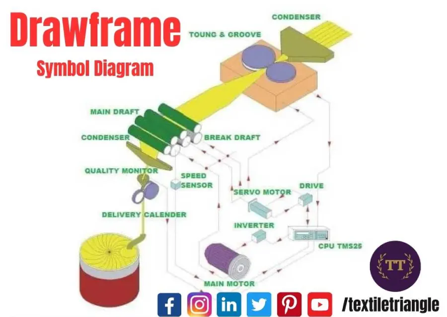
2. Drafting Section
The arrangement of the sliver at the draw frame is carried out by roller drafting method in which the card sliver is passes through two or more pairs of rollers.In the modern draw frames the top roller used are rubber coated and are called as cots while the bottom rollers are steel rollers having fine flutes on their surfaces.The cots exert pressure on bottom rollers and their surface is treated with anti static material.The back cots exert less pressure as compared to the next succeeding cot in the drafting system.
The surface speed of each succeeding pair of rollers is kept more than the previous one.The slower pair of the roller grips the fibre whereas the next faster pair of the rollers draw the fibres forward.This increases the length of the sliver and reduces its linear density by a factor equal to ratio of the surface speed of the fast moving roller to the surface speed of the slow moving roller.This ratio is called as mechanical draft.
The distance between two pair of rollers is called as drafting zone.The distance between the nip lines of the two adjacent pair of roller is called the roller setting.The first pair of roller(at the feed end)is called as back rollers and the last pair of rollers(at the delivery end) is called as front rollers. The roller drafting systems used on various draw frames are of many types.However every roller drafting system is named according to the number of top and bottom rollers it has. Draw frames are available with 4 over 4,3 over 3,4 over 3,5 over 3 and 3 over 4 roller arrangements. All of these arrangements give good results when set appropriately. A 4 over 4 roller drafting system is shown below:
Break draft(Draft in back zone)= V2/V1,
Middle draft(Draft in middle zone)= V3/V2 ,
Main draft(Draft given at the front zone)= V4/V3
Total draft=Break draft*Middle draft*Main draft
=V2/V1*V3/V2*V4/V3
Fibre straightening during drafting
As the fibres are drafted out at the draw frame,the hooked fibres are also straightened out.This is illustrated in below. In this example of simplicity three fibres are shown to be caaught between two pairs of roller. The roller pair(A) is movng at a linear speed of 100 m/min whereas the roller pair (B) is moving 5 times faster at 500 m/min.When the slower hooked fibre(1) held by the nip of roller pair(A) comes in contact with the faster moving fibres(1&2) held by the nip of roller pair(B),the faster fibres (1& 2) will tend to pull the slower fibre(1) and the hooked end will be aligned with other fibres moving in the same direction.
Roller settings
The roller setting which is the distance between the nip lines of the two adjacent pair of rollers is mainly governed the fibre length.The roller setting is kept widest apart in the back zone while it is narrowest in the front zone. This is due to the fact that fibres in the fibres in the back zone will have more hooks and a wider spacing must be given in this zone. When adjusting roller settings,the distance between the nips of the two adjacent rollers should be just wide to let the longest fibre grow. If the spacing is too narrow,the longer fibre will break.If the spacing is too wide,many fibres will float in between the two draft zones.The floating fibres are the ones which are not held by the drafting rollers.The floating fibres can buldge at a point to creat thick and thin places. The succesion of thick places along with the sliver is called is called as drafting wave.Drafting wave may also be caused by worn off cots is machine imperfection.
3. Sliver Condensing Section
The flat fibre web(consisting of several card slivers) exiting the drafting section must be converted in to sliver.The fibre web leaving the front pair of drafting rollers is passed through a converging tube and is guided to designed condensing funnel called as trumpet guide.The degree of condensing at the trumpet guide is essential for providing a good fibre to fibre cohesion to hold better in a sliver.However too much condensing is done then the drawn sliver develops thick places.
4. Coiler Section
The drawn sliver coming out of the calender rollers is passed through a coiler tube fixed on a coiler plate.The fear fixed on the coiler plate help to rotate the coiler tube so that the sliver can be laid in the can in the form of special coils.The can rests on the rotating plate,with the rotation of the plate the an also rotates.The rate of rotation of the can kept slower than the rate of the rotation of the coiler tube.
5. Suction Section
The fibres moves swiftly over the surface of the drafting rollers,dust and lint may be dislodged in to the air.The nose of the suction system on the draw frame is to remove these particles so that they might not get deposited on the surface of the drafting rollers and also to maintain a dust and lint free environment.
Perfect roller drafting
Each fibre in the drafting zone should travel at the speed of the back roller until its leading end reaches the front roller nip,the fibre then gets accelerated instantly to the front roller speed.
Ideal pressure distribution
In ideal pressure distribution-a)Back roller pressure is enlarged,in order to keep fibres move at back roller speed.b)Front roller pressure is more concentrated or narrow ,so that fibres under the influence of the front pressure can change speed near the nip of the front rollers.c)Pressure from the back rollers decreases gradually ,so fibres are not held back while they get accelerated from front roller nip.
Real drafting
In real roller drafting situation,both pressure distribution in the drafting zone and sliver themselves as idle as ones mentioned above.Fibres in a real sliver are of different length and diameters.They are often straight and parallel to the sliver axis.
- Fibre a– The roller exert more pressure on this fibre than the back roller.It has been accelerated to the front roller speed and is fast moving fibre, travelling at the speed of front roller.
- Fibre b– This fibre is under heavy control of the back rollers, It is slow moving fibre.
- Fibre c– This fibre is not under direct control of either roller nip known as floating fibres.
Fibre control in roller drafting
By using control roller and pressure bars, fibres can be control in roller drafting.
Fiber control in roller drafting is a critical aspect of the drafting process in textile production. It involves managing and controlling the movement and behavior of fibers as they pass through the drafting zone between the rollers. Effective fiber control ensures proper alignment, uniformity, and optimal drafting characteristics. Here are some key considerations for fiber control in roller drafting:
- Opening and Blending:
Before entering the drafting zone, fibers are opened and blended to create a loose mass or sliver. Opening refers to the process of separating individual fibers from compacted tufts or bales. Blending involves combining fibers from different sources or bales to achieve a homogeneous fiber mass. Proper opening and blending help ensure consistent fiber distribution and improve subsequent drafting performance. - Drafting Zone Length:
The length of the drafting zone, i.e., the space between the front and back rollers, plays a crucial role in fiber control. It affects the extent of elongation and thinning applied to the fibers. The length is determined based on fiber characteristics, desired drafting ratio, and machine specifications. An appropriate drafting zone length helps achieve the desired drafting effect while maintaining fiber control. - Roller Settings:
Adjusting the roller settings, including nip gap and roller diameter, is essential for fiber control. The roller settings influence the tension, elongation, and thinning of the fibers. Optimal roller settings ensure uniform drafting, prevent slippage or excessive tension, and help maintain fiber alignment. - Roller Surface and Coatings:
The surface finish and coatings of the rollers can impact fiber control. Smooth and uniform roller surfaces minimize friction and fiber disturbance during drafting. Roller coatings, such as rubber or polyurethane, can improve grip and reduce slippage, enhancing fiber control. - Roller Speed Differential:
The speed difference between the front and back rollers creates tension and stretching in the fibers. Controlling the speed differential is crucial for achieving the desired drafting effect and maintaining fiber control. The draft ratio, which is the ratio of the delivery speed to the feed speed, determines the speed differential and elongation of the fibers. - Roller Alignment:
Proper alignment of the rollers is essential for fiber control. Misaligned rollers can cause uneven drafting, fiber disturbances, or slippage. Regular maintenance and alignment checks ensure consistent and effective fiber control. - Fiber Cleaning and Preparatory Processes:
Prior to entering the drafting zone, fibers should undergo appropriate cleaning and preparatory processes to remove impurities, short fibers, or neps. Clean fibers with consistent characteristics facilitate better fiber control during drafting.
Effective fiber control in roller drafting is crucial for achieving uniform drafting, alignment, and optimal elongation of fibers. It contributes to the production of high-quality yarn with desirable characteristics such as strength, evenness, and uniformity. Operators, technicians, and machine settings play vital roles in optimizing fiber control during the roller drafting process.
Roller Arrangements in Drafting Systems
Roller arrangements in drafting systems refer to the configuration and placement of the rollers within a drafting machine or drawframe. The arrangement of these rollers plays a crucial role in controlling the drafting process and achieving desired results in terms of elongation, thinning, and fiber alignment. Here are some common roller arrangements used in drafting systems:
- Bottom Roller – Top Roller Arrangement:
This is the most basic and widely used roller arrangement in drafting systems. It consists of a bottom roller and a top roller pair. The bottom roller is the feed roller, and the top roller is the delivery roller. The material, such as fiber or sliver, passes between these two rollers. The differential speed between the bottom and top rollers causes drafting and elongation of the material. - Bottom Roller – Middle Roller – Top Roller Arrangement:
In some drafting systems, a middle roller is added between the bottom and top rollers. This arrangement provides additional control over the drafting process. The middle roller helps distribute the tension and improves fiber alignment. It allows for more gradual elongation and enhanced drafting quality. - Three-Roller Arrangement:
Another roller arrangement used in some drafting systems is the three-roller arrangement. It consists of three rollers in a triangular configuration. The bottom roller serves as the feed roller, and the top two rollers act as the delivery rollers. This arrangement provides enhanced control over the drafting process, allowing for precise adjustments and improved drafting quality. - Floating Roller Arrangement:
In floating roller arrangements, one or more rollers are mounted on springs or other flexible elements. This arrangement allows the rollers to have some degree of independent movement. Floating rollers help accommodate variations in material thickness, irregularities, or disturbances during the drafting process. They aid in maintaining a consistent draft and reducing drafting defects. - Apron Drafting System:
In an apron drafting system, aprons or belts are used in combination with the rollers to control the drafting process. The material passes between the aprons and rollers, allowing for additional control and improved drafting quality. Apron drafting systems are commonly used in some spinning techniques, such as rotor spinning.
The specific roller arrangement used in a drafting system depends on factors such as the type of fibers or materials being processed, desired drafting characteristics, machine design, and spinning process requirements. Different roller arrangements offer varying levels of control, elongation, and drafting quality. Manufacturers and technicians optimize the roller arrangement to achieve the desired results in terms of fiber alignment, evenness, and strength in the produced strand.
Periodic mass variation in drawn sliver
The numerical values such as U% or CV% are not influenced by the periodic variations. A spectrogram is used to measure the periodic or nearly periodic mass variations in a sliver, roving and yarn by analyzing the frequencies at which faults occur electronically.
C.V.%=1.25U%
The irregularity U% is proportional to the intensity of the mass variations around the mean value. The U% is independent of the evaluating time or tested material length with homogeneously distributed mass variation. The larger deviations from the mean value are much more intensively taken into consideration in the calculation of the coefficient of variation C.V. %. C.V. % has received more recognition in the modern statistics than the irregularity value U%. The coefficient of variation C.V.% can be determined extremely accurately by electronic means.If n slivers are doubled together,the CV of doubles material will be reduced by a factor of 1/√n,or
CVAfter doubling=CVbefore doubling/√n
Where CVbefore doubling is the average CV of the individual slivers before doubling
Limiting irregularity::The limiting irregularity is also expressed as a CV value,denoted as CVlim here.
- Limiting irregularity of an ideal yarn without fibre variability(Synthetic staple):
CVlim(%)=100/√n
- Limiting irregularity of an ideal yarn without fibre variability(Cotton fibre):
CVlim(%) =106/√n
- For wool fibre , CVlim=112/√n
- CVlim(Blend)=√(CV1 lim*T1)2+(CV2 lim*T2)2+………..+(CVn lim*Tn)2/Tb(Count of blend)
Index of Irregularity
I=CVeff/CVlim ,
Where, I=Index of irregularity
CVeff=Effective (Actual irregularity)
CVlim=Limiting irregularity
- Higher draft in drawframe will reduce sliver uniformity, but improve fibre parallelisation and redution in hooks.
- First draw frame package will reduce the periodic mass variation due to piecing
- Wider back roller setting will increase imperfections and lower the strength.
Frequently Asked Questions | FAQs
How can we reduce USTER value of Drawframe machine ?
To reduce the USTER value of a drawframe machine, which measures the sliver unevenness or imperfections, the following steps can be taken:
Optimize Roller Settings: Adjust the roller settings, such as the nip gap and roller speeds, to achieve better control over the drafting process. Fine-tuning these settings can help reduce sliver unevenness and improve overall quality.
Improve Autolevelling: Ensure that the autolevelling system is calibrated and functioning properly. Fine-tune the autolevelling parameters to minimize variations in sliver thickness and improve uniformity.
Check and Clean Drafting Components: Regularly inspect and clean drafting components, such as drafting rollers, aprons, and top combs, to prevent build-up of dirt, fibers, or contaminants that can impact sliver quality.
Fiber Cleaning and Preparation: Ensure that the fibers entering the drawframe are properly cleaned and prepared. Effective opening, blending, and cleaning processes upstream can help reduce impurities and fiber irregularities.
Monitoring and Adjustment: Continuously monitor the sliver quality during operation using sensors or monitoring systems. Make necessary adjustments to the machine settings, autolevelling, or roller arrangement based on real-time feedback to minimize sliver unevenness.
Maintenance and Calibration: Regularly maintain and calibrate the drawframe machine to ensure its optimal performance. Follow manufacturer guidelines for maintenance schedules and procedures.
By implementing these measures, operators can work towards reducing the USTER value and improving the overall quality and uniformity of the sliver produced by the drawframe machine.
How to control A% in drawframe ?
To control A% (imperfections in sliver) in a drawframe, the following steps can be taken:
Optimize Roller Settings: Adjust the roller settings, such as nip gap and roller speeds, to achieve better control over the drafting process and reduce sliver imperfections.
Fine-tune Autolevelling: Calibrate and optimize the autolevelling system to minimize variations in sliver thickness and improve overall quality.
Regular Maintenance: Perform regular maintenance of the drawframe machine, including cleaning and inspection of drafting components, to prevent build-up and ensure smooth operation.
Fiber Cleaning and Preparation: Implement effective fiber cleaning and preparation processes upstream to remove impurities and irregularities that can contribute to sliver imperfections.
Monitoring and Adjustments: Continuously monitor the sliver quality using sensors or monitoring systems, and make necessary adjustments to machine settings and processes based on real-time feedback.
By implementing these measures and ensuring proper control and optimization of the drawframe machine, operators can work towards reducing A% and improving the quality of the sliver produced.
What is meant by doubling in drawframe ?
Doubling in drawframe refers to the process of combining multiple slivers or strands of fibers together to form a single, thicker sliver. This is typically done to increase the total mass or count of the resulting sliver, improve fiber blending, or achieve desired characteristics for subsequent processing stages.
What is function of pressure bar in drawframe ?
The function of a pressure bar in a drawframe is to exert pressure on the fiber sliver as it passes through the drafting zone. The pressure bar helps to control the thickness and density of the sliver, improve fiber alignment, and enhance the drafting process by minimizing slippage between the fibers and the drafting rollers.
What is minimum count variation in cotton drawframe sliver ?
The minimum count variation in cotton drawframe sliver refers to the acceptable level of variation in the linear density or count of the sliver. It is typically specified as a percentage or a numerical value and represents the tolerance for count variations within a given batch or production run. The specific minimum count variation can vary depending on the quality requirements and standards set by the textile manufacturer or industry guidelines.
What is purpose of pressure bar in drawframe ?
The purpose of a pressure bar in a drawframe is to exert pressure on the fiber sliver as it passes through the drafting zone. This pressure helps to ensure better control over the drafting process by reducing slippage between the fibers and the drafting rollers. The pressure bar also aids in improving fiber alignment, reducing irregularities, and achieving a more uniform and consistent sliver thickness.
What is role of pressure bar in drawframe ?
The role of a pressure bar in a drawframe is to exert controlled pressure on the fiber sliver during the drafting process. This pressure helps to enhance fiber alignment, reduce slippage between fibers and rollers, and improve the overall quality and uniformity of the sliver. The pressure bar contributes to maintaining consistent drafting conditions, minimizing variations in sliver thickness, and optimizing the drafting performance of the drawframe machine.
What is total draft of drawframe machine ?
The total draft of a drawframe machine refers to the overall elongation or stretching applied to the fiber sliver during the drafting process. It is the product of the individual draft ratios in each drafting zone of the drawframe. The total draft determines the extent of elongation and thinning of the sliver, which affects its linear density and quality. The specific value of the total draft depends on the machine settings and desired drafting characteristics for a given application.
What is use of pressure bar in drawframe ?
The primary use of a pressure bar in a drawframe is to exert pressure on the fiber sliver during the drafting process. This helps to improve fiber alignment, reduce slippage between the fibers and the drafting rollers, and enhance the overall quality and consistency of the sliver. The pressure bar plays a crucial role in maintaining controlled drafting conditions and achieving optimal drafting performance in the drawframe machine.
Why pressure bars used in drawframe ?
Pressure bars are used in drawframe machines to apply controlled pressure on the fiber sliver during the drafting process. This pressure helps to improve fiber alignment, minimize slippage between the fibers and drafting rollers, and enhance the quality and consistency of the sliver. The pressure bars play a vital role in ensuring effective drafting, reducing imperfections, and achieving desired characteristics in the produced sliver.
What is the draw frame?
The drawframe is a machine used in the textile industry to process fiber slivers or strands. It performs the task of drafting, which involves elongating, thinning, and aligning the fibers to produce a more consistent and uniform sliver. The drawframe utilizes pairs of rotating rollers and various mechanisms to control the drafting process and improve the quality of the fiber material before it is further processed in subsequent stages of spinning.
What is the function of draw frame?
The main function of a drawframe is to perform the process of drafting on fiber slivers. It elongates, thins, and aligns the fibers in the sliver to produce a more consistent and uniform strand. The drawframe improves the quality and evenness of the sliver by controlling the drafting parameters such as roller settings, draft ratio, and fiber tension. It prepares the sliver for subsequent spinning processes by aligning the fibers and reducing any irregularities or imperfections present in the original material.
What is the principle of drawframe?
The principle of a drawframe is based on the concept of drafting, which involves elongating, thinning, and aligning fibers in a sliver to produce a more consistent and uniform strand. It utilizes pairs of rotating rollers that create a speed differential, causing the fibers to undergo controlled elongation and thinning. The drafting process is achieved by adjusting roller settings, controlling tension, and ensuring proper fiber alignment. The principle of the drawframe is to improve the quality and evenness of the sliver, making it suitable for subsequent spinning processes.