Fabric Structure
Warping
The parallel winding of warp ends from many winding packages (cone or cheese) on to a common package (warp beam) is called warping. The operation of winding warp yarns onto a beam usually in preparation for slashing, weaving, or warp knitting, also called warping. The mounting of supply packages in a creel to feed fiber to a process, i.e., beaming or warping.
Requirements of Warping:
1. The tension of all wound ends must be uniform & possibly constant during all the time of withdrawal from supply package.
2. Warp yarn should not impair the physical & mechanical properties of yarn.
3. The tension should be moderate to allow the yarn complete retain its elastic property.
4. Predetermined length of warping should be observed.
5. Th production rate of warp yarn should be high.
6. The surface of warp yarn package must be cylindrical.
Different types of Warping Machines
1. Introduction
Classification of warping methods are given below:
1. Beam warping machine (Direct or High speed warping)
2. Sectional warping machine
3. Ball warping machine
2. Major Components of Warping Machine
A. Creel: Creel is a structure of holding supply packages in textile processes.Function of component of creel are:
- Cone or cheese spindle of high speed & peg for sectional warping
- Thread guide to pass through the yarn in the required way
- Tensioner to keep the yarn always in a uniform tension
- Yarn clearer
- Suction fan
- Breakage indicator
- Stop device
Types of Creel:
- As per the shape (H-shape & V-shape)
- As per the construction (Trolley, chain, magazine, swivel frame creel)
B. Headstock: The major component of warping machine that actually rotates and winds the warp sheet on package (i.e. Warpers beam). Componets are:
- Adjustable V-reed
- Measuring and making device
- Yarn speed controlling device
- Pneumatic pressure unit
- Break assembly
- Driving drum
- Stop motion
- Beam bracket
- Lease rod
3. Types of Warping Machine
A. Beam Warping Machine
It is also called as High speed warping or Direct warping.In high speed warping the yarn is wound parallel on the warping beam.All he yarns are wound at once and simple flanged beam is used.It is very high speed process and is used for making fabric of single colour.
- Yarn is directly wound from cone on to the beam
- This process is suitable for single colour weaving
- The end product is called warp beam and must sent to the sizing department for further process.
Types of Beam warping machine:
- Direct driven or spindle driven
- Surface driven
Features of Direct warping:
- It is used to make common fabrics in large quantities
- It is used to produce weavers beam from single yarn
- The production is high
- The large amount of yarn is required to produce a weavers beam
- Sizing is done
- Simple flanged beam is used and drums are not required
Main parts of Beam warping machine:

- Creel: V-shape creel is used in this type of warping,because it permits high running speeds(up to 1200m/min) and high productivity.
- Expanding comb: The comb has two traverse motion one is horizontal and another is vertical.It is used to place all threads on a width corresponding to the beam width and maintain them in order without entanglement.
- Pressure roll: It is coated with hard card board.The pressure roller is lifted by a hydraulic control device if there is increase in the winding thickness of the yarn on the beam.
- Beam: Beam is used to wound the parallel sheet of yarn ends.
Working principle of Beam warping machine:
In beam warping ,yarns are withdrawn from the single end yarn packages on the creel & directly wound on a beam.This warping can be used in two ways-
- Beam warping can be used to directly produce the weavers beam in a single operation.This is specially suitable for strong yarns that do not require sizing such as continuous filaments & when the number of warp ends on the warp beam is relatively small.This is called direct beaming.
No.of Beams=Total number of warp yarns/Creal capacity
- Beam warping is used to make smaller intermediate beams called warpers beam.These small beams combined later at sizing stage to produce weavers beam. If the weavers beam contains 10000 warp ends,hence 10 warpers beam of 1000 ends each.It is impossible to handle in direct beaming.
B. Sectional Warping Machine
In sectional warping equal length of yarn is first wound in small sections or sheets on a drum.Then from the drum it is transferred to the beam.By this process we directly get the weavers beam.This is two stage methods and is used for making fancy fabrics.
- Yarn is wound firstly wound on to a drum and then wound on to the beam
- This process can be used for single or multicolour weaving
- The end product is called weavers beam and can be directly installed on to the weaving loom.
Main parts of sectional warping machine:

- Dresser: The dresser is the creel element on which the thread coming from the creel and guided by the carriage are wound ,section after section.The dresser or drum is composed of a big sheet steel cylinder with a precisely turned outer surface which bears at its end a series of slope control rulers(knives) ,which form a cone with variable taper.There are however also warping machines with fixed taper.
- Carriage-The carriage have a traverse motion and have the following parts-
- Expanding or warping comb: It has task of positioning all thread of each section on a given width,calculated by the already described method.It has open book shape with its opening angle adjustable at will.
- Guide and metering roller: It is situated at a very short distance from the contact point of the section on the dresser and provide a precise guide to the section and its used to measuring the tension of the section immediately bedore the contact point,to transit this value to the computer.
- Leveling roller: It permits to carry out the warping under low thread tension,and to attain at the same time a compact winding.When processing mono-filament or multifilamet yarns in fine counts which do not stand high compression,it is possible to cut out the levelling roller.
Motions of carriage:
The carriage has two motions:
- A slow traverse motion parallel to the drum axis,which makes the the yarn layers to climp up the dresser cone.this motion called feed,permits the the leaning of the first section on the drum cone and leaning of the subsequent sections on the previous section.
- The motion enables the carriage to move along the section width at each section change.

Tanα=N*S/N*A =S/A
Where, α=angle of cone slope
N=No. of dresser revolutions
A=Feed of carriage per dresser revolutions,S=Avg thickness of wound layer
Working principle of sectional warping–
- Sectional warping is used for short runs specially for fancy pattern fabrics.
- In this case section of warp which may contain up to 1000 ends are first wound on to a drum tapered with a given cone angle.
- So cross wound sections are combined on the drum & thus each layer of warp contains the same number of ends on the drum.
- Then the warp threads together are transferred on to a weavers beam by unwinding the drum.
- In this method warp threads are not necessarily processed in sizing.
- The tension is less uniform
- Production is lesser
- It is less efficient than high speed warping
Calculation in Sectional Warping:
Section number = Total no. of warp yarn / Creel loading capacity
and
Section width = Reed width / No. Of sections
C. Ball Warping Machine
Warping Calculations
Defects and Remedies in Warping
Principles of Operation of Warping Machine
Sizing
Sizing is the process of applying protective coating upon the yarns surface is called sizing. It help to achieve weaving efficiency especially for blended and filament yarns.Sizing increases elasticity of yarn, smoothness and friction resistance.
Objects of Sizing
To improve the weavability of the warp yarn
2. To maintain good fabric quality by reducing hairiness,weakness and by increasing smoothness,strength of yarn.
3. To increase the tensile or breaking strength for cellulose yarn
4. To increase the elasticity
5. To remove the projecting fibres
6. To reduce elastostatic formation for synthetic or blended yarn.
Sizing Ingredient
There are followings sizing ingredients:
- Adhesive substances: The adhesive substances are:
- Carbohydrate
- Wheat-flour
- Rice-flour
- Shagu
- Barly
- Tamarind seed powder
- Potato starch
- Gum
- Carboxyl methyl cellulose
- Poly vinyl alcohol
- Maiza farina
2. Lubricants: The lubricants are:
- Wax
- Animal fat
- Mineral & Vegetable oil
- Tallow
- Soap
3. Antiseptic:
- Salicylic acid
- Zinc chloride
- Phenol
- Emulsifier
- Copper sulphate etc.
different types of Sizing Machines
Working of Sizing
Defects and Remedies in Sizing
Uneven Sizing:
Cause: Due to over sizing
Remedies: Avoid over sizing
Hard Sizing:
Cause: When sizing ingredient applied more in the warp yarn
Remedies: Apply optimum ingredient
Sandy warp:
Cause: Mistake produced due to grind or crushed the size stuff perfectly
Remedies: Be carefull during preparing the size stuff
Size spot:
Cause: During sizing procedure inwards warp yarn, size ingredients must move added gradually into the chemical mixing tank for perfect mixing of chemical. It if it’s non happened there, as well as thus this type of fault is produced.
Remedies-Check guide rollers properly
Shinnery:
Cause: This type of defects produced because of the friction between the drying cylinder as well as warp yarn.
Size dropping:
Cause: This is due to the no optimum viscosity of the solution.
Improper drying:
Cause: Due to over drying
Size stitching:
Cause: When drying volition is non perfect after sizing
Repeating warp streaks:
Cause: Due to improper tension in the yarn
Lappers:
Cause: Due to end breakages
Invisible breaks during sizing
Patches
Sizing Calculations
Size Take-up%: The amount of size material added on the yarn surface is called size take up percentage.
Size take-up%=(Weight of size yarn-Weight of unsized yarn)*100 / Weight of unsized yarn
% of size on warp=Weight of size*100 / Weight of unsized warp
Weight of sized warp=Weight of unsized warp*(100+% of size) / 100
Count of sized yarn=Count of unsized yarn*100/(100+% of size on the warp)
Shuttle Loom
The machine used for weaving process is known as weaving machine or loom.The loom in which the shuttle is used for insertion of weft is known is shuttle loom. There are following shuttle looms are:
- Handloom
- Power loom(Non-automatic loom)
- Automatic loom
1. Handloom: The loom which run by manual efforts i.e. the machine run by the human effort without using any type of mechanical device.
2. Power loom (Non-automatic loom)-The loom which run without manual efforts i.e. the looms which are run by the help of electrical power called power loom.
3. Automatic loom-The loom in which the shuttle take place automatically means the shuttle change does not require man effort.Shuttle will change automatically.
Loom Mechanism
The weaving process consists of three types of mechanism:
1. Primary mechanism
2. Secondary mechanism
3. Auxiliary mechanism
1) Primary mechanism: It is essential mechanism.It is not possible to produce fabric without these mechanism known as primary mechanism. For weaving a fabric, three primary motions are required in the loom are:
* Shedding
* Picking
* Beat-up
a) Shedding: Shedding is the operation by which the warp is divided in to two sheets so that sufficient gap is created for the uninterrupted passage of the weft from one side of the loom to the other.It is the separation of warp threads in to two layers.
b) Picking: Picking is the operation to transfer the pick(weft yarn) from one side of the loom to the other side.In shuttle loom,picking is done from both sides of the loom,however in shuttleless loom it is done from one side of the loom.Shuttle is most traditional mode of picking one and still it is being used in the industry.
c) Beat-up: Beat up is the operation to position the newly inserted pick up to the cloth fell.Cloth fell is the boundary up to which the fabric has been woven i.e pushes or beats the newly inserted length of weft thread in to already woven fabric at a point called fell of cloth.
2) Secondary mechanism: It is the mechanism which is required for making weaving continuous so this mechanism is known as secondary mechanism are two types:
- Take-up motion
- Let-off motion
a) Take-up motion-This motion withdraw the cloth from the weaving area at constant rate as to give the required pick spacing and then winds it on cloth roller.
i) Negative take-up:Take-up roller is driven by dead weight
ii) Positive take-up:Take-up roller is driven by means of train of wheels.
b) Let-off motion-This motion is used for necessary tension on warp sheet,regulate amount of warp yarn delivered by the warp beam during weaving & influence PPI.
i)Negative let-off
ii)Positive let-off
3) Auxiliary mechanism: The mechanism which are useful but not absolutely essential and by using which we get high productivity & good quality of fabric.Auxiliary mechanisms are 5 types:
- Warp protector
- Weft stop motion
- Warp stop motion
- Temples
- Break
a) Warp protector mechanism: This mechanism stop the loom if shuttle gets trapped between the top and bottom layer of shed and prevent the damage of warp,shuttle and reed.
b) Weft stop motion: This motion stop the loom when the weft thread breaks or get exhausted and avoid cracks in fabric.
c) Warp stop motion: This motion stop the loom when the warp thread breaks during the weaving process.
d) Temples: These are metal holder which grip the cloth and hold it at the same width as the warp in the reed & until not wound.
e) Break: Breaks the loom whenever required like when we want to repair broken end.
Automatic Shuttle Loom
The loom in which the shuttle take place automatically means the shuttle change does not require man effort. Shuttle will change automatically. The automatic looms have all the essential motions of weaving namely,
Shedding,
Picking,
Beat-up,
Let-off, and
Take-up.
There are additional motions which are incorporated to make them fully automatic such as warp stop motion, automatic weft replenishing motion, automatic positive let off motion. Weft replenishment on the automatic looms is of two types:
A. Cop changing and
B. Shuttle changing.
These can be run for time without stopping so long as the warp does not break. Superior quality fabrics are manufactured at minimum cost and highest level of weaving efficiency. Additional motions such as the following are also incorporated in the loom to assist the above motions such as weft feeler motion, weft fork motion, shuttle protector motion, weft cutter, etc. speed of these looms can be as high as 200-250ppm (rpm).
Features of Shuttleless Looms are:
1. A large shuttle mass of about 450g (for cotton weft yarn) is employed for transporting a pick of weft which is about 0.2 g/m on the average, leading to a considerable waste of energy.
2. Unguided free flight of shuttle can lead to shuttle fly, abrasive damage of reed and shuttle as also uncontrolled weft tension.
3. Shuttle checking within the confined space of a shuttle box results out of multiple impacts. Consequently the exact location of rest position of shuttle within a box becomes indeterminate, affecting efficient transfer of picking energy during acceleration of shuttle. Moreover such impacts result in damage to shuttle and pirn.
4. Mass of shuttle with full pirn and with near empty pirn can differ by about 10%. As a result the nature of shuttle flight varies in a periodic manner which in turn affects weft tension profile and therefore properties of the resultant fabric.
5. Noise emanating from weft insertion systems employing a conventional shuttle can be as high as 110dB.
6. Shuttle is made of an assembly of various elements which may come apart over a period of time due to multiple and severe impactual cyclic loads. Moreover the major component of shuttle is good wood which is becoming scarce by the day.
Advantage:
* Easy to operate
* More economical
Disadvantage:
* Make more noise
* Warp breaks increase for shuttle
* Production rate is lower
Shuttle Less Loom
Airjet Loom
An air-jet loom is a shuttleless loom that uses a jet of air to propel the weft yarn through the warp shed. It is one of two types of fluid-jet looms, the other being a water-jet loom, which was developed previously. Air-jet looms are capable of weaving plaids, as well as dobby and jacquard fabrics.
Waterjet Loom
Rapier Loom
In principle then a rapier loom might involve a pair of rapiers operating from two ends of fabric selvedge with their associated complex profile of velocities or may even operate with one rapier only that traverses entire fabric width with a velocity profile that is more congenial than that of a double rapier system in so far as weft insertion phase is concerned. However such a rapier has to retract the entire shed width during which fabric production enters an idle phase. Effectively therefore there is not much to choose between the two in terms of weft insertion rate. Additionally such rapier systems when employed on reasonably broad looms need to be of rigid type with associated space wastage. However if instead of inserting a single pick of weft a single rapier inserts a loop of yarn across entire fabric width then the idle production phase as also space wastage can be more than compensated. Evidently not many cloth constructions permit such an option, limiting thus commercial viability of single rapier system.
The rapier head on creel side picks up yarn from designated cone and is carried towards centre of warp shed by the rod. Simultaneously the matching rapier head from opposite side moves in. The picking cycle is completed when both rapiers retreat to their original position, outside the two selvedges. At this instant rapier head opposite to creel holds the weft tip while the other end of weft is held firmly by feeding elements near the magazine creel.
Projectile Loom
A projectile loom operates with a large number of projectiles. While one projectile is in flight many others are on their return journey to starting position adjacent to picking shoe. On being released by brake shoe, projectiles drop onto a conveyor belt which transports them to the picking side. A thumb rule governs total number of projectile required on a loom as function of reed width.
Tappet
Tappets and cam are irregular metallic pieces used to produce an up and down motion in followers and levers.The up and down motion is obtained by giving rotary motion to these pieces.If the follower and lever are required to get a continuous up and down movement, a cam or wiper is used.If the follower and lever are required to produce up and down movement with regular intervals of rest, tappets are used.
There are specific portions in tappets that corresponds to dwell periods i.e. regular intervals of rest for major parts involve in the motion

Dobby
Floor looms that controls all the warp threads using a device called a dobby. The word dobby is a corruption of “draw boy,” which refers to the weaver’s helpers who used to control the warp thread by pulling on draw threads.

Jacquard
Jacquard is a device fitted to a loom that simplifies the process of fabric manufacturing with such complex patter as brocade ,damask.The resulting ensemble of the loom and Jacquard machine is then called a Jacquard loom. Each warp threads rises independently to each other & it produce highest level of warp control.It makes possibility of formation of all type design automatically .It has no limit like other mechanism.
Dobby shedding is complicated and it consumes more than power to tappet shedding it can produce complicated design using maximum heald shaft.

Shedding Mechanism
Shedding is the process to separate the warp thread in to two layers for formation of shed is called shedding.
Various ways of shedding:
1. Tappet shedding
2. Dobby shedding
3. Jacquard shedding
Types of shedding:
1. Bottom closed shedding
2. Centre closed shedding
3. Semi-open shedding
4. Open shed
Tappet Shedding
In the tappet shedding, ups and down movements are obtain by giving rotatory motion to tappet.Tappets and cam are irregular metallic pieces used to produce an up and down motion in followers and levers. The up and down motion is obtained by giving rotary motion to these pieces. If the follower and lever are required to get a continuous up and down movement, a cam or wiper is used.If the follower and lever are required to produce up and down movement with regular intervals of rest, tappets are used.
Generally there are two types of tappet shedding:
1. Negative tappet shedding
2. Positive tappet shedding
Generally for small figuring pattern tappet is used.For tappet shedding mechanism at maximum 12 heald shafts is used.
1) Negative tappet shedding:
In a tappet shedding mechanism,if the tappet controls only one movement,either an upward or downward movement of the heald shaft,then the shedding is known as negative tappet shedding.The heald shafts are return by some external devices like spring,dead weights,roller etc.
Lifting-Mechanically
Lowering-Spring
2) Positive tappet shedding:
In positive tappet shedding mechanism,if tappets control both upward and downward movements of the heald shaft,then shedding is known as positive tappet shedding.
Lifting and lowering both are mechanically.

Dwell Period:
The tappet should be made in such a way that healds will remains stationary while the shuttle passses through the shed.This stationary time is known as Dwell of heald or pause
Picking Mechanism
Picking is the operation to transfer the pick(weft yarn) from one side of the loom to the other side.In shuttle loom,picking is done from both sides of the loom, however in shuttleless loom it is done from one side of the loom. Shuttle is most traditional mode of picking one and still it is being used in the industry.
Picking is divided as:
1. Negative Picking (Conventional)
a)Over picking
b)Under picking
i)Side lever
ii)Side shaft
iii)Cone
2.Positive picking(Unconventional)
1) Negative picking mechanism: In this mechanism a carrier known as shuttle carries the weft yarn in a package called conventional picking i.e.the picking mechanism in which we use the shuttle for insertion of weft thread through shed called conventional or negative picking.
a) Over Picking:
It is the type of conventional or negative picking system in which the motion is transferred by means of a cone so also known as cone over pick mechanism.

Working: When the bottom shaft rotates the nose of the tappet also rotates and strike to cone this cause a partial rotary movement to vertical shaft, the picking arm thus swing inwards with sufficient velocity to drive the picker, the shuttle being in contact with the tip of the picker is pushed across the shed and picking arm return to its original position by spring the cone is always keep in the contact with tappet by spring and this motion repeated from another side means in one shaft rotation 2 pick inserted.
b) Under pick mechanism:
If the fulcrum of the picking arm is below the level of shuttle box then the picking mechanism is known as under pic mechanism.
Types of under pick mechanism–
i) Cone under pick mechanism
ii) Side lever under pick mechanism
iii) Side shaft under pick mechanism
i) Cone under Pick Mechanism:
This is negative/Conventional type of picking mechanism in which the picking shaft contain picking tappet having nose bit and a cone is fixed to side shaft. This causes rotation of the picking shaft. As a result, the picking stick, which is attached to the uppermost end of picking shaft, swing in a horizontal plane over the loom and transmits the motion to shuttle through picking strap and picker guided by a spindle.

ii) Side lever under pick:
1)The circular disk received motion from the bottom shaft. The disk contain a bowl named picking bowl able to push down the picking shoe of side lever.
2) Side lever of loom pivoted with loom frame and the up-down motion of side lever is controlled by fixed guide.
3) Side lever is connected with elbow of picking stick which attached with returning spring on the top of rocking shaft.
4) Each picking stick contains picker which push the shuttle through the passage.
Working Principle:
Due to motion of circular disk the picking bowl strike on picking shoe. For the strike lever pushed down. The front side of the lever push the elbow of picking stick, the result picking stick move forward and it hit the picker which push the shuttle to insert weft and the pushing force is enough to send the shuttle to opposite shuttle box.

iii)Side Shaft under Pick:
The side shaft makes partial angular motion. When the side shaft rotates in an anti-clockwise direction, it pulls the picking stick forcefully. The picker attached on the top of the picking stick hits the shuttle. Thus shuttle travels from one shuttle box to another shuttle box.
Beat Up Mechanism
Beat up is the operation to position the newly inserted pick up to the cloth fell.Cloth fell is the boundary up to which the fabric has been woven i.e pushes or beats the newly inserted length of weft thread in to already woven fabric at a point called fell of cloth.It consists in driving the last pick of weft to the fell of the cloth. This is accomplished with the help of a reed fixed in the sley. The sley is given a sudden and quick movement towards the fell of the cloth by the cranks in the crankshaft. The sleywood runs from one shuttle box to another, and when at its backward movement, the shuttle travels over its race.
There are different types of beat-up mechanism in weaving, depending on several factors. But mainly, two types of beating is considered in general based on the operating element.
- One is crank and crank-arm beat-up (used in shuttle loom), and
- another is cam best up (mostly used in the shuttleless loom).
However, the related parts of the beating process remain constant irrespective of whether the main motion comes from crank or cam. The basic difference in between this is the source of motion of the sley, whereas this sley motion ultimately controls the overall parameters of beat-up.

Description: The crankshaft gets drive from motor via motor pulley and machine pulley. The crankshaft has two cranks. These cranks transform the rotary motion into swinging motion. The reed cap is connected by crank arm to crank of the crankshaft. Again the reed is connected between reed cap and sley. There is sley sword under the sley that is bolted to the rocking shaft. There is also shuttle box on the sley. Now the crank gives the swinging motion to the sley by crank arm. When the sley is moving towards the heald shaft at certain position the shuttle passes through warp shed. Again when the sley is coming towards the front rest at last position the reed pushes the last pick to the previous pick of cloth. This is the beating-up motion and the cloth increases in lengthwise in this way.

Sley Eccentricity Ratio: The ratio r/l, where r is the radius of the crank circle and l is the length of the crank arm, is called the sley eccentricity ratio, e.
e=r/l
Let Off Mechanism
This motion is used for necessary tension on warp sheet,regulate amount of warp yarn delivered by the warp beam during weaving & influence PPI. The let off motion is the secondary motion of weaving which is used to release the warp yarns from the weavers beam so that weaving can take place. It is a mechanism which provides the facility to Let off the warp yarn from the beam.let-off is a device for controlling the delivery and tension of the warp during weaving. Let-off mechanism controls the rotation of the beam on a weaving, warp knitting or other fabric is forming machine where the beam is driven mechanically
i)Negative let-off
ii)Positive let-off
i) Negative let off motion: Negative let-off is a mechanism for controlling the rotation of the beam on a weaving, warp knitting or other fabric forming machine where the beam is pulled round by the warp against a breaking force applied to the beam.
In this system the tension of the warp is regulated by the friction between chain and the beam ruffle. The friction is controlled by dead weight on the weight lever and the distance of dead weight from the pivot. Heavier the dead weight and longer the distance of it from the pivot lesser the let-off.
The warp beam dia gradually decreases as weaving proceeds. So it’s necessary to increase the let-off rate. If the dead weight is kept on the same place, the let-off rate will remain unchanged. So an experienced worker is required to change the dead weight gradually with the change of the warp beam dia. As a result irregular tension occurs and the rate of yarn breakage may increase.
ii) Positive Let Off Motion: In the case negative let off motion the warp is pulled off the beam and the tension is regulated by slippage in a braking system. In a positive let-off motion, the beam is driven through a positive mechanism where no slippage takes place. This latter type of mechanism is seldom used and in most cases the tension is controlled by a mechanism driving the warp beam, which allows a certain loss of motion (or slippage) whenever the tension increases. Basically these are crude negative feed back automatic control systems which are related to controls such as are used in auto-leveling during sliver production.
These mechanisms are sometimes considered positive, but in reality they are semi-positive.Positive let-off motion is defined as a motion in which the weaver’s beam is turned at a rate that maintains a constant length of warp sheet between cloth fell and weaver’s beam, the means of applying warp tension being separate from the beam-driving mechanism.
Take Up Mechanism
This motion withdraw the cloth from the weaving area at constant rate as to give the required pick spacing and then winds it on cloth roller.
i)Negative Take-Up:Take-up roller is driven by dead weight
ii)Positive Take-Up:Take-up roller is driven by means of train of wheels
a) Intermittent positive take up
i) Direct(5 wheel take up)
ii) Indirect(7 wheel take up)
b)Continuous positive take up
Negative Take-Up Mechanism:
In this, the take-up roller is driven by the dead weight placed on the leaver according to the degree of pushing or beat up of weft in to fell of the cloth.So the uniformity in pick spacing is not maintained.
5-Wheel Take Up Motion:
In this motion we use a train of 5- wheels. It is a positive and continuous take-up motion and the 5 – wheel used are given below.
i) Ratchet wheel
ii) Change wheel
iii) Stud wheel
iv) Stud Pinion
v) Emery roller end wheel
When the sley moves backward the stud in the slot of take-up lever also moves backward and the pushing pawl moves forward and push one or two teeth of ratchet wheel. Due to this the ratchet wheel moves and the motion transfers to change wheels from change wheel the stud wheel also rotates and from the stud wheel the motion get transfers to stud pinion. The stud Pinion is in contact with the emery roller end wheel. So it will rotate the emery roller end wheel and the motion is transferred to take up roller. The take up roller rotates and the cloth gets wind up on to the cloth roller pick by pick.
It consist of a stud at the bottom of sley sword. The stud is in the slot of monkey tail lever or take up lever which has its fulcrum at a point C. A pushing pawl is resting on the ratchet wheel , a change wheel and this change wheel is gear with stud wheel. On the same shaft of stud wheel a stud pinion is mount, which is in contact with the emery roller end wheel. This emery roller is in contact with the take-uke roller.

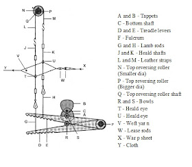
7-Wheel Take-Up Motion:
Seven wheels take-up motion is an intermittent take up motion. This mechanism receives motion from the sley sword. When the crankshaft rotates, the slay sword receives to and fro motion from the crankshaft. A connecting rod is used to connect the finger and slay the sword.
A- Ratchet wheel
B – standard wheel
C – Change wheel
D – Change pinion
E – Compound wheel
F – Compound pinion
G – Take up roller wheel
H – Take up roller
I – Pushing pawl
J – Pulling pawl
K – Finger fulcrum
L – finger
Sley sword to connecting rod. Connecting rod to monkey tail. Monkey tail to pawl. Pawl to ratchet wheel. Ratchet wheel to standard wheel. Standard wheel to change wheel. Change wheel to sewing wheel. Sewing wheel to stud wheel. Stud wheel to stud pinion. Stud pinion to take up wheel. Take up wheel to take up,The motion is primarily imparted from the sley sword. The sley sword is connected to the slay that gets motion from crank shaft and the crank shaft gets motion from motor by gearing. At the bottom of sleysword a connecting rod is connected which passes the motion to the monkey tail.
The monkey tail is fulcrum with two pawls: the upper is holding pawl and lower is pulling pawl. These two pawls are mounted freely to the ratchet wheel which is connected with the standard wheel by shaft. Over the standard wheel the change pinion is geared. The change pinion is connected with the stud pinion by shaft and the stud wheel is geared with the stud pinion upon it. The swing pinion is connected with the stud wheel and the cloth take-up roller wheel is geared with the swing pinion.
Various Stop Motions
a) Warp Protector Mechanism: This mechanism stop the loom if shuttle gets trapped between the top and bottom layer of shed and prevent the damage of warp,shuttle and reed.
b) Weft Stop Motion: This motion stop the loom when the weft thread breaks or get exhausted and avoid cracks in fabric.This motion able to stop the loom when a weft breaks or runs out of the pirn (weft package). Warp protector motion: This motion protect the warp threads by stopping the loom when the shuttle fails to reach, the selvedge side and box properly into either the shuttle box during picking.
c) Warp Stop Motion: This motion stop the loom when the warp thread breaks during the weaving process.
d) Temples: These are metal holder which grip the cloth and hold it at the same width as the warp in the reed & until not wound.
e) Break: Breaks the loom whenever required like when we want to repair broken end

Fabric Geometry
Cloth Cover
A fabric is a structure composed of two sets of yarns i.e. warp and weft.Normally the count of warp and weft yarns are different and no. of these threads per inch is also different in the cloth. Cloth cover is basically dependent upon counts of warp and weft yarn ends/inch, pics/inch within the cloth. This geometry effects the properties such as air permeability, stiffness, drapeability and tensile strength of the fabric.


P=1/n
n=No. of threads per unit ends
Cloth Cover=d*n
=D*1/P
=D/P
C1=Warp cover=d1/P1
C2=Weft cover=d2/P2
%Cover=d/P*100
Total Cover(C)=C1+C2-C1C2
Cover of fraction part=d1d2/P1P2
=C1C2P1P2/P1P2
=C1C2
Cover Factor=d/P*28, P=1/n and d=1/(28√Ne)
Cover Factor(K) =n/(28√Ne)*28
=n/√Ne
- If a square plain weave is considered with warp and weft count equal an ends & picks per inch equal.
The fraction d/P=1/√3
So,Cover factor(K)=1/√3*28=16.2
- If K1 is the cover factor of warp and K2 is the cover factor of weft thread in a fabric ,then the fraction of area covered by warp and weft in the fabric is
Cloth Cover(Kc)=K1+K2-(K1K2/28)
Fabric Structure & Design
Basic elements of Fabric Design
Fabric is depends on the fabric structure ,classified as woven, non-woven and knitted fabrics.Basic elements of woven fabric designs are given below as:
- Weave plan
- Drafting plan
- Lifting plan
- Denting plan
1) Weave plan: Weave plan illustrates the interlacing of ends & picks in the fabric under consideration. It shows the up & down of each yarn in a fabric sample. Graph paper is used to draw weave plan.

This is a representation of design of a plain weave:
- The vertical line (column) represents warp yarn.
- The horizontal line (row) represents weft yarn.
- ←↓Represents repeat unit.
- ‘X’ represents warp over weft.
- Empty box represents weft over warp.
- # Represents starting point.
2) Drafting plan: Drafting plan indicates the number of heald shafts required to make a design and also indicates the threading of warp through heald eyes of heald shafts it is drawn top of the weave plan.

3) Lifting plan: Lifting plan indicates the selection of heald shafts to be lifted or lowered on each successive insertion of weft or pick. Lifting plan is drawn at the right side of the weave plan.

4) Denting plan: The process of inserting warp yarn through dent is called denting and the plan that indicate the order in which denting is done is called denting plan. This is done for keeping uniform spacing between yarns of warp sheets. Usually two yarns are passed through each dent.
Plain Weave
Derivatives of plain weave: The derivatives of plain weaves are:
- Warp rib(Regular, irregular)
- Weft rib(Regular, irregular)
- Matt weave(Regular, irregular)
1) Warp rib: When float run in the warp direction ,warp rib form. warp ribs are two types:
a)Regular warp rib: The condition of construction of regular warp rib is no. of warp upwards are equal to the number of warps down and its minimum repeat is 2*2.
b) Irregular warp rib: Its minimum repeat is 2*5.When no. of warp up does not equal to no. of warp down.
2)Weft rib: When float run in the weft direction, weft rib form .It may be defined as plain weave in which each pick passes alternatively over or under or more than 2 ends . It is normally found in weft face structure.
a)Regular weft rib: When number of up weft is equal to number of weft down is called regular weft rib.
b)Irregular weft rib: When number of up weft does not equal to number of weft downs is called irregular weft rib.
Extra Warp & Weft Design
Warp Backed Design
Weft Backed Design
Double Cloth Construction
1. Introduction
The simplest type of double cloth consists of two series of weft threads and two series of warp threads, one series of each kind forming an upper of face fabric and the other an under or backed fabric. Weft weave rib is employed for both back and face textures. Double cloths are the fabrics, which contains two layers of yarns those are woven one above the other and stitched together. Double cloths have at least two series of warp yarns, and two series of weft yarns, namely face and back. Double cloths fabrics are popularly known as two ply fabrics. The upper layer is formed by interlacing the face warp yarns with the face weft yarns, and the lower layer is formed by interlacing the back warp yarns with the back weft yarns. The two layers may be only loosely connected in which, each may be readily identified as a different entity, or they may be so intricately stitched or tied together that they appear to form a complex single structure.
2. Objective of Double Cloth
- To improve thermal resistance of the fabric
- To improve appearance of the fabric and hand feel of the fabric
- To improve air permeability
3. Types of Double Cloth Fabric
- Self stitches double cloth
- Centre stitches double cloth
- Double cloth stitches by thread interchanged
- Double cloth stitches by cloth interchanged
- Alternate single ply and double ply construction
1. Self Stitches Double Cloth
This double cloth is constructed on the principle of self-thread stitching. In this cloth, the face fabric is formed by the interlacement of the face warp and face weft threads and the back fabric is formed by the interlacement of the back warp and back weft threads. The two fabric layers are stitched together at intermediate points by either face/back warp or face/back weft or both. Construction of self stitches double cloth are:
a) Stitching from face to back
b) Stitching from back to face
c) Combination stitching
2. Centre Stitches Double Cloth
These double cloths are constructed on the principle of centre thread stitching. In these cloths, besides a face and back series of threads, there is a third series of threads those are introduced as stitching threads at different intervals. The stitching can be done in warp way, weft way or in both the way. Basically, stitching threads stay in between the face layers and the back layers of the cloth and are visible on the face or back at the stitching points.
3. Double Cloth Stitches by Thread Interchanged
It is constructed on the principle of stitching by thread interchange. This fabric is like the self-stitched double cloths as the stitching is done by means of either the face or the back threads themselves. Basically, the dissimilarity is that, a group of face threads interlace or stitch with another group of back threads at regular intervals.
4. Double Cloth Stitches by Cloth Interchanged
This cloth is constructed on the principle of cloth interchange. In these cloths, the cloth layers change places at intervals. The firmness of this type of structural cloth depends on the frequency of the exchange of the face and back layers of the cloth. They are used from finished fabric to apparel, coats & jackets etc.
5. Alternate Single Ply and Double Ply Construction
Geometrical & Floral Design
Design is defined as any arrangement of lines, forms, colour, and textures.
Damask & Brocade Design
1. Damask Design
In true damask figured fabric, a weft sateen figured is formed upon a warp sateen ground or vice versa and the structure is describe as reversible. The term damask, however, is also applied to cloths in which the figured portions are developed in diverse ways upon a sateen ground, the texture being then known as a one-sided damask . Cotton and linen damasks are used in the white state for table napery ; cotton or linen warps are crossed with worsted weft, and in the dyed condition the cloths (termed union – damask) are used for table-cloths, hangings, etc., while fine silk damasks are used for a variety of purposes. Designs in which diverse weaves are employed in the figure are woven in ordinary or full-harness mountings. Small reversible damask designs are also frequently woven in a similar manner, in which case it is necessary for the binding weaves of the figure and ground to be cut upon the cards since each end in the repeat is controlled by a separate needle and a card used for each pick. There are two chief types :
- Pressure Harness,
- Twilling Jacquard.

The objects of each arrangement are to enable each needle of the jacquard to control two or more consecutive ends, and each card to act for two or more successive picks ; and to simplify and reduce the cost of painting out designs and card cutting. In each mounting the ends are controlled both by and independently of the figuring cards.In designing for the twilling jacquard the counts of the design paper is in the proportion of ends per inch . picks per inch hooks per needle picks per card .For example, assuming that a cloth contains 96 ends and 140 picks per inch, and that 32 hooks are connected to 12 needles, and there are 10 picks to three cards
96 ends /32/12:140 picks/10/3 =12×14 design paper
Tapestry Structure
Almost every class of fabric structure is used for tapestry and upholstery purposes. ranging from cloths composed of one warp and one weft to those in which two or more series of threads are introduced in one or both directions. Some of the textures are mono-coloured, and the designs range from simple but striking effects to the boldest and most intricately developed styles of figures. Elaborate figure ornamentation is also combined with diversity of colour, whilst in certain textures the design is entirely due to colour the figure being formed chiefly for the purpose of displaying different hues and tones (extra warp, extra weft ,pile structure).
Weft Face Tapestry: The tapestry structure is the design is due to diversity of colouring in the weft. Two series of ends are employed, arranged as follows : 2 binding ends of 2/80’s cotton, 2 figuring ends of 2/20’s cotton, 60 ends per inch. The weft is 2-ply 10’s worsted, with 14 picks of each colour per inch.
Warp Face Tapestry: A class of tapestry cloth, in which the design is due to colour is also largely made which has a warp-rib surface, the pattern in this case being chiefly due to employing two, three, or more differently coloured series of figuring ends. Two strongly contrasting figuring wefts one very dark and the other very light are, however, introduced, both of which form an effect on the surface in conjunction with each warp colour, and also produce small parts of the ornament independently. With three warp colours, which is a common arrangement, eight effects can be produced in any part of the cloth six by combining each warp colour with each weft colour, and two by the wefts separately. Further, planting the warp colours is largely resorted to, and very great diversity of colour ornamentation is thereby obtained in the width of a fabric.
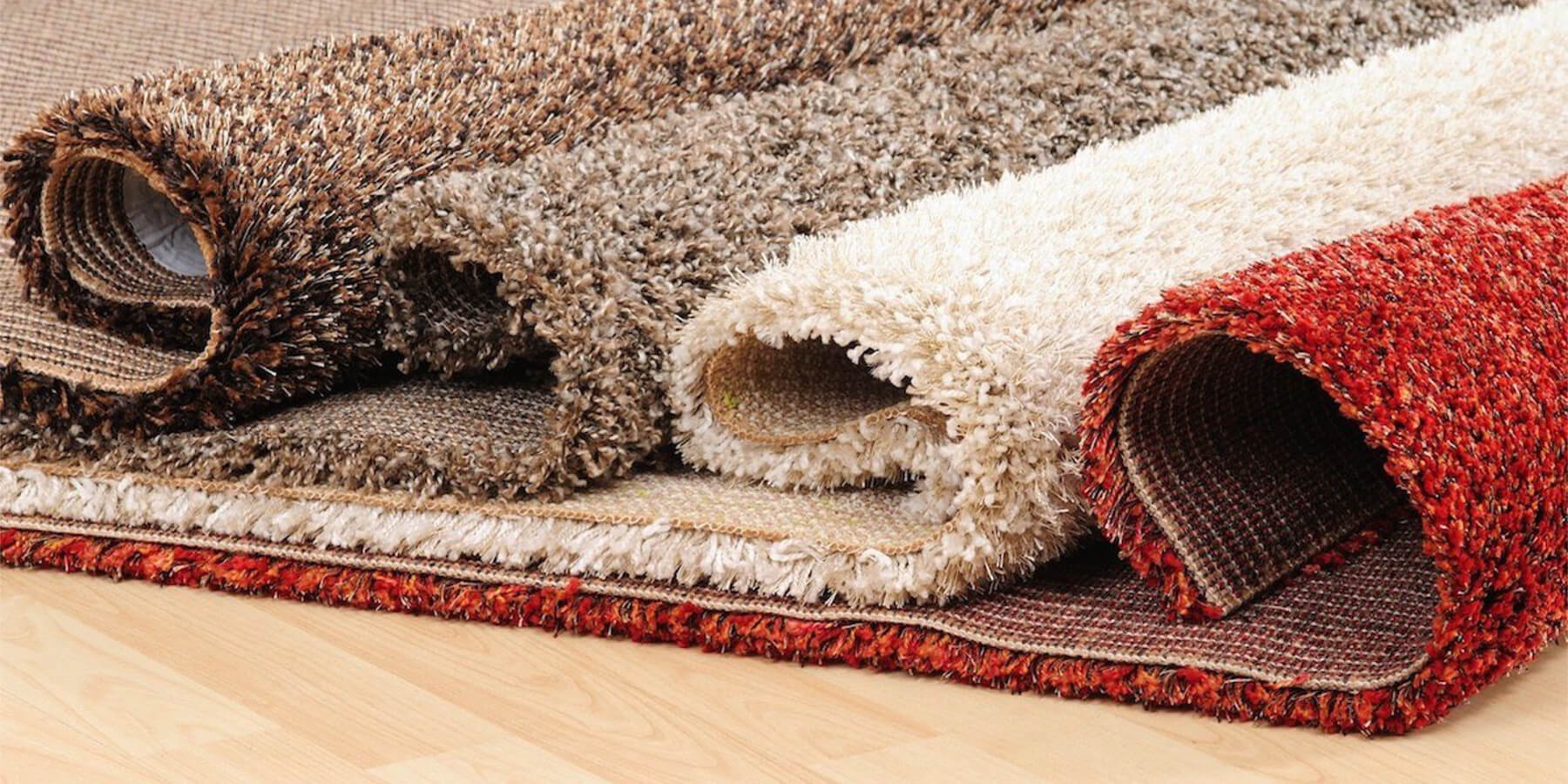
Carpet & Textile Design
Carpet is floor covering fabric . It consists of upper layer of pile attached to a backing .Mostly synthetic fibres are used like polypropylene ,nylon or polyester and and usually consists of twisted tufts which are often heat-treated to maintain their structure. Carpets can be from wall to wall or smaller in size such as area rugs.The knotted pile carpet are said to have originated in the 3rd or 2nd millennium BC in West asia, or the armenian Highland. Carpet weaving in India can be traced to the beginning of the Mughal empire wherein under the patronage of the Mughals, Indian craftsmen adopted Persian techniques and designs. Akbar, a Mughal emperor, introduced the art of carpet weaving to India, during his reign. The Mughal emperors patronized Persian carpets for their royal courts and palaces. The carpets woven in India showed the classic Persian style of fine knotting. The Indian carpets are known for their designs with attention to detail and presentation of realistic attributes. In India, carpet industry uses wool, silk, acrylic and Jute.
Types of carpet-Carpets are followings types:
- Woven carpet
- Needle felt carpet
- Knotted carpets
- Hand tufted carpets
1)Woven carpet-The carpets are made on looms similar to traditional handloom. The piles can either be cut pile or loop pile. Many coloured yarns are used in making of these carpets and this process of weaving produces intricate patterns. Woven carpets are produced in Kashmir, Mirzapur, Bhadohi, Jaipur and agra in India.2)Needle felt carpet-These carpets are more technologically advanced as compared to woven carpets . Needle felts are produced by intermingling and felting individual fibers using barbed and forked needles and hence forming an extremely durable carpet. These carpets are generally used in areas which are prone to friction due to high footfall.3) Knotted Carpets- These carpets are made on upright or vertical looms. A knotted pile carpet is a supplementary weft cut-loop pile carpet where the structural weft threads alternate with a supplementary weft that rises at right angles to the surface of the weave. Knotting by hand is most prevalent in oriental carpets. Carpets produced in Kashmir are also hand knotted.4)Hand tufted carpets-In such carpets there is a pile injected into a backing material, which is then bonded to a secondary backing made of a woven fabric to provide stability. This is the most common method of manufacturing of domestic carpets for floor covering purposes in the world. Common motifs include scrolling vine networks, arabesques, palmettes , cloud bands, medallions, and overlapping geometric compartments. animals and humans are not depicted in the persian imagery because Islam is the dominant religion in this part of the world which forbids their depiction. Persian influenced imagery of trellis, vines, medallions, paisleys etc is seen in most of the Indian carpets. The majority of these carpets are wool and silk.
The warp pile weave– The pile warp during weaving takes up much more rapidly than the ground warp, the difference in length varying according to the depth of the wires and the frequency in which the pile threads are raised over the wires. In an ordinary plain pile structure the pile warp may require to be from five to twelve times the length of the ground warp. During weaving, in order that the pile face will not be injured, the temples act only on the selvages, and in winding the cloth on to the cloth beam the underside is brought in contact with the friction beam. When the pile is long, however, the cloth is not wound on to a beam, but is passed directly into a box or other receptacle.
The weft structure of carpet– A fabric in which the design is due to the interchange of two differently coloured wefts. figuring end, as shown in the heald-and-harness draft given at A in Fig. 221. In some cases the figuring ends are single, but if they are two-ply they should be drawn separately through double eyed mails in order that they will spread out. and give a fuller appearance to the cloth. If an ordinary form of jacquard is used two cards are cut from each horizontal space of First card, cut the blanks ; second card, cut the marks. The healds are operated in 2-and-2 order, and the complete weaves are produced in the figure and ground respectively. The cloth is perfectly reversible, a dark figure on a light ground being formed on one side, and a light figure on a dark ground on the other side.